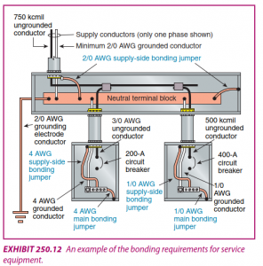
The main bonding jumper and the system bonding jumper perform the same function. And that is to connect the Equipment Grounding Conductor (bare or green wire) to the grounded neutral conductor at either at the transformer location (separately derive system) or the first panel supplied by the transformer.
Although they perform the same function, the two terms are used to distinguish themselves from each other. The main bonding jumper is installed at the incoming service equipment. The system bonding jumper is any bonding jumper in a downstream separately derived system (transformer).
For example if the facility receives 480 volts at the incoming service, there will be one main bonding jumper. And if the facility has three downstream transformers (480 volt DELTA to 208 volt WYE), each transformer (or first panelboard) will have the system bonding jumper.
Additional info:
In a grounded system, the primary function of the main bonding jumper and the system bonding jumper is to create the path for the ground fault current between the Equipment Grounding Conductor and the grounded (neutral) conductor.
Table 250.102(C)(1) (which looks really familiar with Table 250.66 for sizing grounding electrode conductors) is used to establish the minimum size of the main and system bonding jumpers. Unlike the grounding electrode conductor, which carries current to the earth (ground) via the connection to a grounding electrode like the water pipe or concrete encased electrode, the main and system bonding jumpers are placed directly in the supply side ground fault current path.

